Dissecting the Camera Matrix, Part 1: Extrinsic/Intrinsic Decomposition

So, you've been playing around a new computer vision library, and you've managed to calibrate your camera... now what do you do with it? It would be a lot more useful if you could get at the camera's position or find out it's field-of view. You crack open your trusty copy of Hartley and Zisserman, which tells you how to decompose your camera into an intrinsic and extrinsic matrix --- great! But when you look at the results, something isn't quite right. Maybe your rotation matrix has a determinant of -1, causing your matrix-to-quaternion function to barf. Maybe your focal-length is negative, and you can't understand why. Maybe your translation vector mistakenly claims that the world origin in behind the camera. Or worst of all, everything looks fine, but when you plug it into OpenGL, you just don't see anything.
Today we'll cover the process of decomposing a camera matrix into intrinsic and extrinsic matrices, and we'll try to untangle the issues that can crop-up with different coordinate conventions. In later articles, we'll study the intrinsic and extrinsic matrices in more detail, and I'll cover how to convert them into a form usable by OpenGL.
This is the second article in the series, "The Perspective Camera, an Interactive Tour." To read other article in this series, head over to the introduction page.
Prologue: Getting a Camera Matrix
I'll assume you've already obtained your camera matrix beforehand, but if you're looking for help with camera calibration, I recommend looking into the Camera Calibration Toolbox for Matlab. OpenCV also seems to have some useful routines for automatic camera calibration from a sequences of chessboard images, although I haven't personally used them. As usual, Hartley and Zisserman's has a nice treatment of the topic.
Cut 'em Up: Camera Decomposition [?]
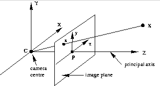
To start, we'll assume your camera matrix is 3x4, which transforms homogeneous 3D world coordinates to homogeneous 2D image coordinates. Following Hartley and Zisserman, we'll denote the matrix as P, and occasionally it will be useful to use the block-form:
where M is an invertible 3x3 matrix, and C is a column-vector representing the camera's position in world coordinates. Some calibration software provides a 4x4 matrix, which adds an extra row to preserve the z-coordinate. In this case, just drop the third row to get a 3x4 matrix.
The camera matrix by itself is useful for projecting 3D points into 2D, but it has several drawbacks:
- It doesn't tell you where the camera's pose.
- It doesn't tell you about the camera's internal geometry.
- Specular lighting isn't possible, since you can't get surface normals in camera coordinates.
To address these drawbacks, a camera matrix can be decomposed into the product of two matrices: an intrinsic matrix, K, and an extrinsic matrix, \([R \, |\, -RC ]\):
The matrix K is a 3x3 upper-triangular matrix that describes the camera's internal parameters like focal length. R is a 3x3 rotation matrix whose columns are the directions of the world axes in the camera's reference frame. The vector C is the camera center in world coordinates; the vector t = -RC gives the position of the world origin in camera coordinates. We'll study each of these matrices in more detail in later articles, today we'll just discuss how to get them from P.
Recovering the camera center, C, is straightforward. Note that the last column of P is -MC, so just left-multiply it by \(-M^{-1}\).
Before You RQ-ze Me... [?]
To recover R and K, we note that R is orthogonal by virtue of being a rotation matrix, and K is upper-triangular. Any full-rank matrix can be decomposed into the product of an upper-triangular matrix and an orthogonal matrix by using RQ-decomposition. Unfortunately RQ-decomposition isn't available in many libraries including Matlab, but luckily, it's friend QR-decomposition usually is. Solem's vision blog has a nice article implementing the missing function using a few matrix flips; here's a Matlab version (thanks to Solem for letting me repost this!):
function [R Q] = rq(M)
    [Q,R] = qr(flipud(M)')
    R = flipud(R');
    R = fliplr(R);

    Q = Q';
    Q = flipud(Q);
Easy!
I'm seeing double... FOUR decompositions! [?]
There's only one problem: the result of RQ-decomposition isn't unique. To see this, try negating any column of K and the corresponding row of R: the resulting camera matrix is unchanged. Most people simply force the diagonal elements of K to be positive, which is the correct approach if two conditions are true:
- your image's X/Y axes point in the same direction as your camera's X/Y axes.
- your camera looks in the positive-z direction.
Solem's blog elegantly gives us positive diagonal entries in three lines of code:
# make diagonal of K positive
T = diag(sign(diag(K)));

K = K * T;
R = T * R; # (T is its own inverse)
In practice, the camera and image axes won't agree, and the diagonal elements of K shouldn't be positive. Forcing them to be positive can result in nasty side-effect, including:
- The objects appear on the wrong side of the camera.
- The rotation matrix has a determinant of -1 instead of 1.
- Incorrect specular lighting.
- Visible geometry won't render due to a having negative w coordinate.
In this case, you've got some fixing to do. Start by making sure that your camera and world coordinates both have the same handedness. Then take note of the axis conventions you used when you calibrated your camera. What direction did the image y-axis point, up or down? The x-axis? Now consider your camera's coordinate axes. Does your camera look down the negative-z axis (OpenGL-style)? Positive-z (like Hartley and Zisserman)? Does the x-axis point left or right? The y-axis? Okay, okay, you get the idea.
Starting from an all-positive diagonal, follow these four steps:
- If the image x-axis and camera x-axis point in opposite directions, negate the first column of K and the first row of R.
- If the image y-axis and camera y-axis point in opposite directions, negate the second column of K and the second row of R.
- If the camera looks down the negative-z axis, negate the third column of K.
Leave R unchanged.Edit: Also negate the third column of R. - If the determinant of R is -1, negate it.
Note that each of these steps leaves the combined camera matrix unchanged. The last step is equivalent to multiplying the entire camera matrix, P, by -1. Since P operates on homogeneous coordinates, multiplying it by any constant has no effect.
Regarding step 3, Hartley and Zisserman's camera looks down the positive-z direction, but in some real-world systems, (e.g. OpenGL) the camera looks down the negative-z axis. This allows the x and y axis to point right and up, resulting in a coordinate system that feels natural while still being right-handed. Step 3 above corrects for this, by causing w to be positive when z is negative. You may balk at the fact that \(K_{3,3}\) is negative, but OpenGL requires this for proper clipping. We'll discuss OpenGL more in a future article.
You can double-check the result by inspecting the vector \(\mathbf{t} = -RC\), which is the location of the world origin in camera coordinates. If everything is correct, the sign of \(t_x, t_y, t_z\) should reflect where the world origin appears in the camera (left/right of center, above/below center, in front/behind camera, respectively).
Who Flipped my Axes?
Until now, our discussion of 2D coordinate conventions have referred to the coordinates used during calibration. If your application uses a different 2D coordinate convention, you'll need to transform K using 2D translation and reflection.
For example, consider a camera matrix that was calibrated with the origin in the top-left and the y-axis pointing downward, but you prefer a bottom-left origin with the y-axis pointing upward. To convert, you'll first negate the image y-coordinate and then translate upward by the image height, h. The resulting intrinsic matrix K' is given by:
Summary
The procedure above should give you a correct camera decomposition regardless of the coordinate conventions you use. I've tested it in a handful of scenarios in my own research, and it has worked so far. Of course, if you have any problems with this approach, I'm eager to hear about them, just leave a message in the comments, or email me.
In the next article, we'll investigate the extrinsic matrix in more detail, with interactive demos.
Posted by Kyle Simek