Calibrated Cameras in OpenGL without glFrustum
Update (June 18, 2013): added negative signs to definitions of C' and D'.
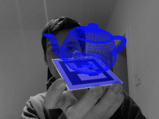
Update (August 19, 2013): James Gregson has posted an implementation in C++. I haven't tested it myself, but it looks quite nice.
You've calibrated your camera. You've decomposed it into intrinsic and extrinsic camera matrices. Now you need to use it to render a synthetic scene in OpenGL. You know the extrinsic matrix corresponds to the modelview matrix and the intrinsic is the projection matrix, but beyond that you're stumped. You remember something about gluPerspective, but it only permits two degrees of freedom, and your intrinsic camera matrix has five. glFrustum looks promising, but the mapping between its parameters and the camera matrix aren't obvious and it looks like you'll have to ignore your camera's axis skew. You may be asking yourself, "I have a matrix, why can't I just use it?"
You can. And you don't have to jettison your axis skew, either. In this article, I'll show how to use your intrinsic camera matrix in OpenGL with minimal modification. For illustration, I'll use OpenGL 2.1 API calls, but the same matrices can be sent to your shaders in modern OpenGL.
glFrustum: Two Transforms in One
To better understand perspective projection in OpenGL, let's examine glFrustum. According to the OpenGL documentation,
glFrustum describes a perspective matrix that produces a perspective projection.
While this is true, it only tells half of the story.
In reality, glFrustum does two things: first it performs perspective projection, and then it converts to normalized device coordinates (NDC). The former is a common operation in projective geometry, while the latter is OpenGL arcana, an implementation detail.
To give us finer-grained control over these operations, we'll separate projection matrix into two matrices Persp and NDC:
Our intrinsic camera matrix describes a perspective projection, so it will be the key to the Persp matrix. For the NDC matrix, we'll (ab)use OpenGL's glOrtho routine.
Step 1: Projective Transform
Our 3x3 intrinsic camera matrix K needs two modifications before it's ready to use in OpenGL. First, for proper clipping, the (3,3) element of K must be -1. OpenGL's camera looks down the negative z-axis, so if \(K_{33}\) is positive, vertices in front of the camera will have a negative w coordinate after projection. In principle, this is okay, but because of how OpenGL performs clipping, all of these points will be clipped.
If \(K_{33}\) isn't -1, your intrinsic and extrinsic matrices need some modifications. Getting the camera decomposition right isn't trivial, so I'll refer the reader to my earlier article on camera decomposition, which will walk you through the steps. Part of the result will be the negation of the third column of the intrinsic matrix, so you'll see those elements negated below.
For the second modification, we need to prevent losing Z-depth information, so we'll add an extra row and column to the intrinsic matrix.
where
The new third row preserve the ordering of Z-values while mapping -near and -far onto themselves (after normalizing by w, proof left as an exercise). The result is that points between the clipping planes remain between clipping planes after multiplication by Persp.
Step 2: Transform to NDC
The NDC matrix is (perhaps surprisingly) provided by glOrtho. The Persp matrix converts a frustum-shaped space into a cuboid-shaped shape, while glOrtho converts the cuboid space to normalized device coordinates. A call to glOrtho(left, right, bottom, top, near, far) constructs the matrix:
where
When calling glOrtho, the near and far parameters should be the same as those used to compute A and B above. The choice of top, bottom, left, and right clipping planes correspond to the dimensions of the original image and the coordinate conventions used during calibration. For example, if your camera was calibrated from an image with dimensions \(W \times H\) and its origin at the top-left, your OpenGL 2.1 code would be
glLoadIdentity();
glOrtho(0, W, H, 0, near, far);
glMultMatrix(persp);
Note that H is used as the "bottom" parameter and 0 is the "top," indicating a y-downward axis convention.
If you calibrated using a coordinate system with the y-axis pointing upward and the origin at the center of the image,
glLoadIdentity();
glOrtho(-W/2, W/2, -H/2, H/2, near, far);
glMultMatrix(persp);
Note that there is a strong relationship between the glOrtho parameters and the perspective matrix. For example, shifting the viewing volume left by X is equivalent to shifting the principal point right by X. Doubling \(\alpha\) is equivalent to dividing left and right by two. This is the same relationship that exists in a pinhole camera between the camera's geometry and the geometry of its film--shifting the pinhole right is equivalent to shifting the film left; doubling the focal length is equivalent to halving the dimensions of the film. Clearly the two-matrix representation of projection is redundant, but keeping these matrices separate allows us to maintain the logical separation between the camera geometry and the image geometry.
Equivalence to glFrustum
We can show that the two-matrix approach above reduces to a single call to glFrustum when \(\alpha\) and \(\beta\) are set to near and \(s\), \(x_0\) and \(y_0\) are zero. The resulting matrix is:
where
This is equivalent to the matrix produced by glFrustum.
By tweaking the frame bounds we can relax the constraints imposed above. We can implement focal lengths other than near by scaling the frame:
Non-zero principal point offsets are achieved by shifting the frame window:
Thus, with a little massaging, glFrustum can simulate a general intrinsic camera matrix with zero axis skew.
The Extrinsic Matrix
The extrinsic matrix can be used as the modelview matrix without modification, just convert it to a 4x4 matrix by adding an extra row of (0,0,0,1), and pass it to glLoadMatrix or send it to your shader. If lighting or back-face culling are acting strangely, it's likely that your rotation matrix has a determinant of -1. This results in the geometry rendering in the right place, but with normal-vectors reversed so your scene is inside-out. The previous article on camera decomposition should help you prevent this.
Alternatively, you can convert your rotation matrix to axis-angle form and use glRotate. Remember that the fourth column of the extrinsic matrix is the translation after rotating, so your call to glTranslate should come before glRotate. Check out this previous article for a longer discussion of the extrinsic matrix, including how to it with glLookAt.
Conclusion
We've seen two different ways to simulate a calibrated camera in OpenGL, one using glFrustum and one using the intrinsic camera matrix directly. If you need to implement radial distortion, it should be possible with a vertex shader, but you'll probably want a high poly count so the curved distortions appear smooth--does anyone have experience with this? In a future article, I'll cover how to accomplish stereo and head-tracked rendering using simple modifications to your intrinsic camera parameters.
Posted by Kyle Simek